


1. Introduction
2. Test Site and Ground Condition
3. Spt and Dynamic Cone Penetration Tests
4. Pile Load Tests
5. Comparison with Pile Load Test Results
6. Conclusions
1. Introduction
The standard penetration test (SPT), which has been widely used in Korea, has many usability and suitability whose in determining various soil properties or strength parameters. For intermediate material (IGM) or soft rock cores are recovered in fragments because of joint structures, a dynamic cone penetration test such as Texas cone penetrometer test (TCPT) was proposed as a surrogate method to quantify geomaterial strength of the IGM or soft rock (Nam and Vipulanandan, 2010). During SPT or dynamic cone penetration tests, hammer energy is an important factor to evaluate and calibrate N values. In order to measure hammer energy, an instrumented SPT rod was developed considering that stress waves transferring on rods during SPT or cone driving are the same as stress waves transferring on piles due to pile driving (Lee and Lee, 2005).


From the instrumented rod, the pile drive analyzer (PDA), a high-strain dynamic test to determine the force and velocity response of a pile to an impact force applied axially by a driving hammer at the pile top, collected strain and acceleration measurements during hammer driving. The PDA immediately converted these strain and acceleration signals to force and velocity values. After high strain dynamic data were collected in the field, they were analyzed with a case pile wave analysis program (CAPWAP). Finally, the CAPWAP estimated the end bearing capacity of piles. The CAPWAP is based on the wave equation model, which analyses the pile as a series of elastic segments and the soil as a series of elasto-plastic elements with damping characteristics, where stiffness represents static soil resistance and damping represents dynamic soil resistance (Alvarez, et. al, 2006).
By applying the instrumented SPT rod and the PDA to SPT or dynamic cone penetration tests, these tests can develop stress waves transferring on rods during SPT or cone driving. Then, stress waves can be taken by the PDA and analyzed to estimate unit bearing capacities of piles by the CAPWAP as illustrated in Fig. 1. The instrumented SPT rod was applied to SPT or dynamic cone tests, such as Texas cone penetrometer test (TCPT), modified Texas cone penetrometer test (MTCPT) and Korea Expressway Corporation cone penetrometer test (KCPT). MTCPT and KCPT were newly applied to easy access for the cone into the NX hole because the diameter of the TCPT cone is almost the same as the NX boring size widely used in Korea.
Since the SPT is an essential in-situ test to design pile capacities, the SPT with the instrumented rod can be a simple index for estimating pile capacities. In order to evaluate this concept, SPT and cone penetration tests and a total of 2 pile load tests were performed on the field site in this study.
2. Test Site and Ground Condition
To predict the end bearing capacity of piles with instrumented SPT rods, SPT and several types of dynamic cone tests, ground investigations and field pile load tests were conducted. The test site was located at the construction site of Donghongcheon Interchange overpass in the Chuncheon- Hongcheon Expressway in Korea. For the site investigation, the following tests were performed as marked in Fig. 2, such as “Standard Penetration Test (SPT), KS F2307-87”, “Texas Cone Penetration Test (TCPT)”, “Modified Texas Cone Penetration Test (MTCPT)”, “Korea Expressway Corporation Cone Penetration Test (KCPT)”, “Piezoncone Test (CPT)”, “Pressuremeter Test (PMT)”, and “Dilatometer Test (DMT).” Detailed results of test results except SPT and dynamic cone tests can be referred in Park et. al (2010). Ground condition of the test sites was determined by boring tests and elastic wave tests. The ground profile consisted of 6 layers: reclamation soil (surface to 8.5 m), paddy soil (8.5 to 9.2 m), colluvium soil (9.2 to 13.5 m), weathered soil (13.5 to 18.3 m), weathered rock (18.3 to 20.3 m) and soft rock (20.3 m to 33.6 m).
Table 1. Details of drilling rigs | |||
Equipment | Excavation Method | Hammer Lifting and Falling | Instrument |
Automatic Hammer | Water Jetting Rotary Boring | Chain Rotating | PDA, SPT Rod |
|
(a) Photo of dynamic cone tests with instrumented SPT rod |
|
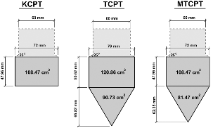
(b) Dimension of dynamic cones |
Fig. 3. Dynamic cone tests with instrumented SPT rods |
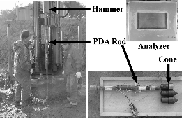
Based on the results of SPT and several types of dynamic cone tests with instrumented SPT rods, CAPWAP was carried out to predict the end bearing capacity before piling constructions; and then, these predicted results were compared with results obtained from pile load tests on production piles.
3. Spt and Dynamic Cone Penetration Tests
In this study, an automatic hammer with instrumented SPT rod was used for SPT, TCPT, MTCPT and KCPT. Table 1 and Fig. 3 show their corresponding details. Instrumented SPT rods with a PDA were used to get force and velocity waves. Then, these waves went through CAPWAP to calculate end bearing capacities.
Two sets of SPT were conducted at intervals of 1.5 m in A1 and A2 as shown in Fig. 3. One set of TCPT was conducted at intervals of 1.5 m as marked on Fig. 3 according to the Texas Department of Transportation geotechnical design manual (TxDOT, 2000). Cones were connected to the bottom of the rods, and were lowered to the bottom of boring holes. Then, the hammer (0.76 KN) connected to the top of the rods was dropped from a height of 61 cm to measure penetration depth. In regular soils, just as the SPT, the number of hits needed to penetrate 30 cm into a cone was calculated. When the ground was too strong and it was difficult to penetrate 30 cm, the cone was hit 100 times, and the penetrating depth at that time was written, for example, as 30/100 (30 mm penetrated at 100 hits). Since the cone is strong, TCPT can be applied to intermediate geomaterial (IGM) or rocks that the SPT cannot penetrate (Nam, 2006).
Since the diameter of the TCPT cone is almost the same as the NX boring size widely used in Korea, MTCPT, that reduces the TCPT cone diameter to 72 mm with the same area ratio of the cone to sleeve for TCPT, is conducted at the test site as shown in Fig. 3. KCPT, that removes the cone part from MTCPT as shown in Fig. 3, was also applied in this study. Hence, tests to analyze differences of end bearing capacities of piles obtained from SPT and various dynamic cone penetration tests including TCPT, SPT, MTCPT and KCPT installed with the instrumented SPT rods were conducted at the test site.
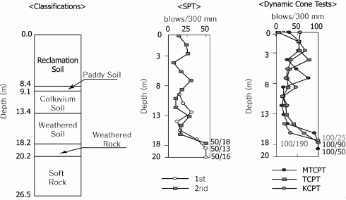
Fig. 4 shows the results of SPT and dynamic cone penetration tests (TCPT, MTCPT and KCPT). The results from dynamic cone penetration tests were similar regardless of their tests, and their distribution in layers was similar to results obtained from SPT.
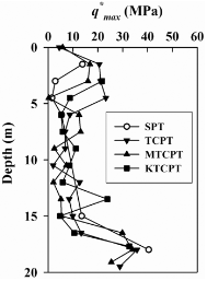
These test results obtained from dynamic cone penetration tests and SPT were analyzed in CAPWAP to estimate predicted ultimate end bearing capacities which are shown in Fig. 5. In this study, an ultimate end bearing capacity predicted by dynamic cone penetration tests and SPT with the instrumented SPT rod was named as q*max. The predicted end bearing capacities of weathered rock, where the pile tip is located, were distributed between 31 MPa and 45 MPa. Even though there were some variations in each test, when there was inconsistency of grounds, distribution of q*max was relatively similar in each test.
4. Pile Load Tests
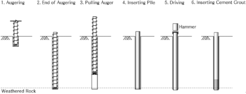
To evaluate q*max obtained from CAPWAP analysis on dynamic cone penetration tests and SPT with instrumented SPT rods, two static pile load tests were conducted on two production piles (TP-1 and TP-2). The pre-bored steel pipe piling method was used for test pile construction, which is very common in Korea. Construction procedure is shown in Fig. 6 and details are as follows: the auger was used to excavate weathered rock and the steel pipe pile with a diameter of 508 mm was inserted and driven. After the final driving, cement grout was injected to pile bases and sides.
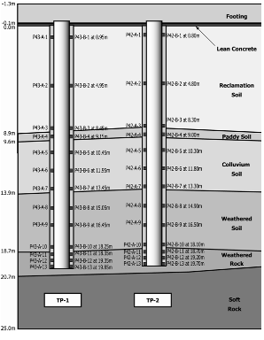
After cement grout was cured, static pile load tests for the two fully instrumented test piles were conducted with load transfer analysis. Information of test piles instrumentation and static pile load tests are shown in Fig. 7. Based on the results of static pile load tests, q-w (end bearing-displacement) curves for test piles are produced as shown in Fig. 8. From the q-w curve, ultimate end bearing capacities by the load test [qmax (load test)] of TP-1 and TP-2 could be determined as about 8.1 MPa and 7.7 MPa by taking their maximum values.

5. Comparison with Pile Load Test Results
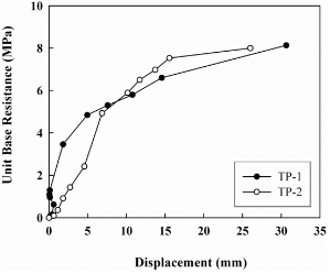
To compare q*max with qmax (load test), the average of q*max values around the pile tip (18 m ~ 21 m) was selected as 34.8 MPa from Fig. 5, and the average of qmax (load test) for TP-1 and TP-2 was also selected as 7.9 MPa form Fig. 8. The qmax (load test) was 23 % of q*max. Based on the limited data, an ultimate end bearing capacity of a pile (qmax) can be predicted as follows:
qmax = 0.23 q*max
where, q*max is an ultimate end bearing capacity predicted by dynamic cone penetration tests and SPT with the instrumented SPT rod.
It is noted that this correlation can be applied only to pre-bored steel pipe piles with a diameter of 508 mm embedded into weathered rocks. This correlation should be applied to other types of piles only after careful consideration. This study suggests a prediction method for the end bearing capacity of the pile by conducting CAPWAP analysis with instrumented SPT rods for SPT or dynamic cone penetration tests. If further studies are carried out for various grounds and piles to gain more reliability, this prediction method can have a wide variety of uses.
6. Conclusions
In this study, force and velocity waves obtained by applying instrumented SPT rods for SPT, and dynamic cone penetration tests were analyzed with CAPWAP to predict the end bearing capacity of the pile. Then, this prediction result was compared with that from field static pile load tests. Results of this study are as follows:
(1)In various dynamic cone penetration tests, the number of hits and penetration values were similar regardless of test types, and distribution results of SPT and dynamic cone penetration tests were similar according to change in ground layers.
(2)Predicted end bearing capacity (q*max) was estimated by conducting the CAPWAP analysis on force and velocity waves obtained from dynamic cone penetration tests and SPT. Although there were some variations in q*max according to test methods, considering the inconsistency of ground, q*max distribution was relatively similar in each test.
(3)To get end bearing capacities (qmax) of piles by SPT or cone penetration tests with the instrumented rod, two pile load tests were conducted to get measured end bearing capacities [qmax (load test)] for comparing predicted and measured capacities. Based on the comparison of q*max and qmax (load test), a correlation of qmax = 0.23 q*max was proposed.
(4)Using this correlation of qmax = 0.23 q*max, end bearing capacities (qmax) of piles can be easily determined by SPT or cone penetration tests with the instrumented rod. However, this correlation is based on pre-bored steel pipe piles with a diameter of 508 mm embedded into weathered rocks and should be applied to other types of piles only after careful consideration.