

1. Introduction
2. Wheel-soil Interaction Mechanics
2.1 Terrain Characteristics under Stress Condition
2.2 Rigid Wheel-deformable Terrain Interaction Model
3. Single Wheel-soil Interaction Testbed
4. Lunar Soil Simulant and Experimental Setup
4.1 Korean Lunar Soil Simulants (KLS-1)
4.2 Wheel Designs
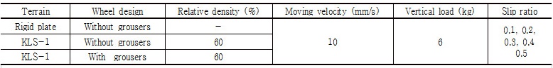
4.3 External Conditions
4.4 Experimental Procedure
5. Results and Analysis
5.1 Performance of Wheel on Rigid Plate
5.2 Performance of Wheel Mobility on KLS-1
6. Conclusion
1. Introduction
Since 1959, the Soviet Union and United States have started lunar exploration program, followed by various kinds of lunar exploration activities from other developed countries. Recently, there have been research programs on rovers for lunar exploration in South Korea. In order to accomplish difficult missions on the moon, there is a continuous need for developing an unmanned exploration rover with high performance which can adapt to the complex environment on the moon and pass the soft soil and negotiate obstacles successfully. In the stage of lunar rover’s development, rover’s locomotion performance on the deformable terrain should be investigated in order to plan the moving path. In order to improve negotiation and mobility performance, optimizing rover wheel’s design is very important. Therefore, investigating mechanical characteristic of wheel-soil interaction has a critical sig-ni--ficance for optimization of wheel design and development of lunar rover with high mobility performance (Ding et al., 2011a).
A variety of approaches to investigate wheel-soil interac-tion performance have been developed and used. One of the empirical methods was developed by US Army Water-ways Experiment Station (WES). This method can evaluate vehicle traction performance with respect to ground cha-racteristics by cone index. However, this empirical method has limitation in predicting certain performance parameter of tyres accurately (Gee-Clough, 1978). Recently, numerical simulation methods which use computer technology (i.e., FEM, DEM) to simulate the model for the traction of a rover wheel on deformable terrain are widely applied to this research field (Liu et al., 1996; Nakashima et al., 2010). It also has limitations in simulating large, dis-continuous terrain deformation. To tackle these problems mentioned above, semi-empirical approaches using wheel- terrain theoretical model and physical properties of soil for evaluating vehicle performance on terrain have been developed. A pioneering work in terramechanics was conducted by Bekker, which came up with the relation between rolling resistance and vertical stress for rigid wheel rolling on the soft soils using Bekker pressure- sinkage equation (Bekker, 1956). Bekker and Wong’s model determined the wheel performance metrics such as torque, drawbar pull, motion resistance, slope angle and so on (Wong, 2010). When the drawbar pull comes up, the shearing action of wheel on the soil causes it to slip. Since the drawbar pull and resistance is a function of slip, the relationships between the drawbar pull and slip of a vehicle wheel are used to evaluate the mobility performance of vehicle. Recently, in planetary researches, due to small dimension of rover wheels and cost of experiments, single wheel testing is thought to be a simple and efficient way to investigate rover-wheel traction per-formance under various situations with different terrain types. Until now, many research works have been done on the study of locomotion performance of small rigid wheel on terrestrial soil such as sand.
In this study, a single-wheel testbed was developed and used to experimentally evaluate traction performance of rigid wheel on deformable soil in terms of drawbar pull, torque and slip-sinkage versus slip ratio under different wheel configuration and vertical load. As planetary rover can get stuck into loose soil, wheel with grousers has been studied because it has significant influence on wheel’s performance (Liu et al., 2008; Sutoh et al., 2012). As introduced in previous studies to implement and satisfy the task of Korean lunar exploration, two kinds of wheels, one with grousers and the other without grousers were applied to investigate and compare rover wheel’s motion performance. In addition, rover’s mobility highly depends on mechanical properties of terrain. Due to the limitation of use of water and organic material in the moon, properties of lunar regolith are clearly distinguished from terrestrial soil (Heiken et al., 1991). Due to the limited quantity of available lunar soils, it is very difficult to carry out experiments on the real lunar soils. Therefore, to satisfy and accomplish the reliable analysis of wheel mobility performance, Korean lunar soil simulant (KLS-1) having similar physical and geotechnical properties of real lunar soil was developed by Ryu et al. (2015) and utilized to simulate lunar terrain in this study.
Though some previous studies aimed at similar experi-mental investigation, this study is distinguished from them in terms of utilization of Korean rover wheel and Korean lunar soil simulant. Thus, we believe this study could contribute to the demonstration of the mobility of Korean Lunar Rover in lunar environment condition for Korean Lunar Exploration Project.
2. Wheel-soil Interaction Mechanics
The analysis of mechanical characteristics between lunar rover wheel and soil interaction is the basis of analyzing the lunar rover’s mobility performance. The analysis of mechanical characteristics wheel-soil interaction is related to the terrain characteristics and mechanical model of wheel-soil interaction.
2.1 Terrain Characteristics under Stress Condition
The semi-empirical approach proposed by Bekker (1960) is used to decompose the deformation of soil vertically and horizontally, corres-ponding to normal pressure characterization and shearing characterization, respectively.
A vehicle applies normal load to the terrain, which results in sinkage. This causes motion resistance (Wong, 2010). Soil is considered as deformable material. To predict the normal pressure distribution on vehicle-terrain interface, the pressure-sinkage relationship for deformable terrain can be defined using Bekker’s equation (Bekker, 1960) as follows:
 (1)
(1)
Where p is the normal pressure added on the wheel, b is the smaller dimension of a contact rectangular plate; n, kc, and  are pressure-sinkage parameters for the Bekker equation, z is sinkage, b is width of contacting plate.
A vehicle applies shear load to the terrain surface through its running gear, which results in the development of thrust and associated slip (Wong, 2010). To predict the tractive performance of vehicle, it is essential to understand the shear stress-shear displacement relationship.
As the lunar soil is plastic soil, its characterization of the shearing behavior can be evaluated based on Janosi’s shearing model (Janosi, 1961). According to this model, the relationship between shear stress of soil and shearing displacement is shown as follows:
 (2)
(2)
 (3)
(3)
Where c is the apparent cohesion of soil,  is the maximum shear strength of soil,
  is the internal friction angle of soil, k is shear deformation modulus, and j is shearing deformation.
2.2 Rigid Wheel-deformable Terrain Interaction Model
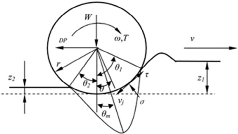
Performance of an off-road vehicle refers to its ability to overcome motion resistance, to develop drawbar pull, to negotiate grade, and to accelerate straight-line motion (Wong, 2010). Fig. 1 shows a picture of interaction force distribution of rigid wheel moving on soft soil. In Fig. 1, r is wheel radius,  is the total sinkage of wheel,
  is the slip sinkage,
  is the wheel-soil interaction angle,
  is the entrance angle,
  is the exit angle,
  is the maximum stress angle,
  is the wheel angular velocity, v is wheel travelling velocity, W is normal load, T is traction torque, DP is drawbar pull,
  and
and  are normal stress and shear stress on wheel-soil contact surface, respectively.
The drawbar pull plays an important role in the evaluation of vehicles’ traction performance. Drawbar pull is developed from soil thrust beneath a moving wheel. Drawbar pull is the net force used to measure tractive ability of vehicles. Drawbar pull (DP) indicates the difference between the thrust F and the sum of all resisting forces R on the vehicles. Wong’s model denotes DP as follows (Wong, 1967):
 (4)
(4)
Where b is the width of wheel.
When a wheel moves on soft soil, shearing action takes place on the wheel and terrain interface, which was illustrated in the last section. Consequently, there is a relative movement (or shear displacement) between wheel and terrain in horizontal direction, which results in slip.
According to Wong (2010), slip generally happens when the lunar rover is moving on the deformable regolith, consequently leading to different wheel velocity from rover travelling velocity. Therefore, slip ratio is a way of expressing the slipping behavior of the wheel. It should be considered to determine the vehicle acceleration. The definition of slip ratio and relationship between shear displacement and slip ratio are expressed by:
 (5)
(5)
 (6)
(6)
Where v is the actual moving speed of the vehicle, ωr is the wheel’s velocity which is equal to the product of angular speed ω and radius of wheel r.
As drawbar pull is a function of shear strength in equation (4), shear strength is related to shear displacement in equation (2),shear displacement is related to slip ratio in equation (6), drawbar pull is also a function of slip ratio.
3. Single Wheel-soil Interaction Testbed
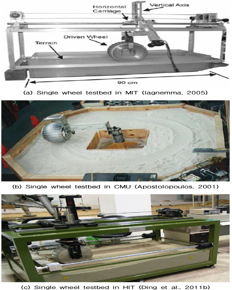
Until now, there are various kinds of testbed developed for researches on the motion of a robotic wheel with small dimensions. Fig. 2 (a) shows a single-wheel testbed which was first developed for planetary rovers in Massachusetts Institute of Technology (MIT) (Iagnemma, 2005). This testbed was used to conduct the experiments of “Rocky” wheel traction performance. It is used to measure drawbar pull, driving torque, wheel velocity and carriage velocity, and also analyze the force of wheel-soil interaction under different slip ratio by means of controlling wheel velocity and carriage velocity. A single wheel testbed shown in Fig. 2 (b) developed by Robotics Institute in Carnegie Mellon University is used to perform characterization of “Nomad” locomotion with measuring driving power, endurance and behavior of the wheel’s drive unit (Apostolopoulos, 2001). Fig. 2 (c) shows a testbed developed in Chinese State Key Laboratory of Robotics and System in Harbin Institute of Technology (HIT) is also used to measure parameters such as drawbar pull, sinkage, slip ratio and driving torque values (Ding et al., 2011b).
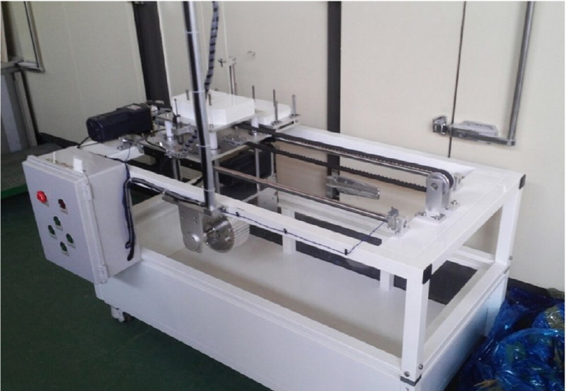
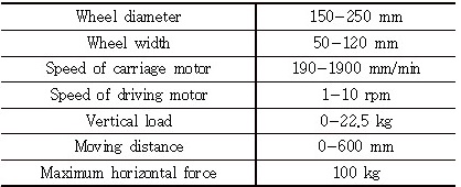
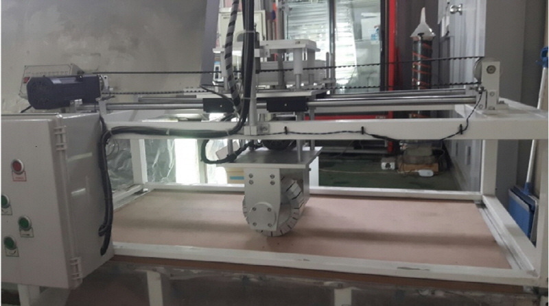
In this research, the single wheel-soil interaction testbed shown in Fig. 3 was developed to measure the wheel drawbar forces, torques and sinkage. This testbed dis-tinguished from other apparatus as the soil box below can be separated from the upper part which is favorable for the experiment in the freezing chamber in KICT. However, experimental results under freezing condition were not included in this paper. The size of soil box of the testbed is 2000 mm × 600 mm × 500 mm. It was designed to conduct experiments on a wheel with a diameter ranging from 150 mm to 250 mm and width ranging from 50 mm to 120 mm. The testbed consists of a driving motor, a carriage motor, LVDT, a counterweight system, and a torque sensor. The driving motor and the carriage motor are used to make the wheel and vehicle body move independently. The slip ratio can vary by controlling the linear velocity of the wheel carriage in the horizontal direction and angular velocity of the wheel. LVDT is used for measuring wheel singkage on the soil. The load added on the wheel can be controlled by a counterweight system attached upon the wheel carriage. The detailed information of the testbed is shown in Table 1.
4. Lunar Soil Simulant and Experimental Setup
4.1 Korean Lunar Soil Simulants (KLS-1)
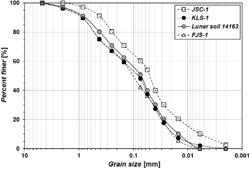
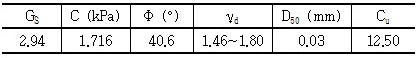
In order to validate reliable mobility of rover wheel’s mobility performance, the experiments were carried out on the Korean lunar soil simulant (KLS-1). Korean Lunar soil Simulant was developed by KICT in 2014 to offer simulant lunar terrain for lunar rover’s motion performance tests. KLS-1 was made from basalt in Yeoncheon through crushing, screening, grinding, sieving and recomposition (Ryu et al., 2015). A group of laboratory tests were carried out to measure the geotechnical properties of KLS-1. Particle size distribution is considered as one of the most fundamental parameters to evaluate the geotechnical cha-racteristic. The test results showed that the particle size distribution of KLS-1 matched with real lunar soil and other lunar soil simulant such as JSC-1 and FJS-1 as shown in Fig. 4. Other geotechnical properties from direct shear test, relative density test and specific gravity test shown in Table 2 were also similar to those of other lunar soil simulants such as JSC-1 and FJS-1. In addition, since the relative density of lunar soil is 65 ± 3% in depth of 0-15cm from lunar surface, in keeping with the lunar regolith condition of surface layer, the relative density of soil was prepared as 60% in experiments (Mitchell et al., 1974).
4.2 Wheel Designs
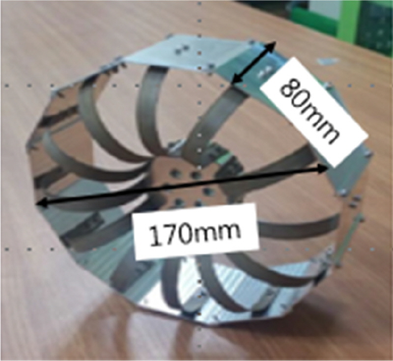
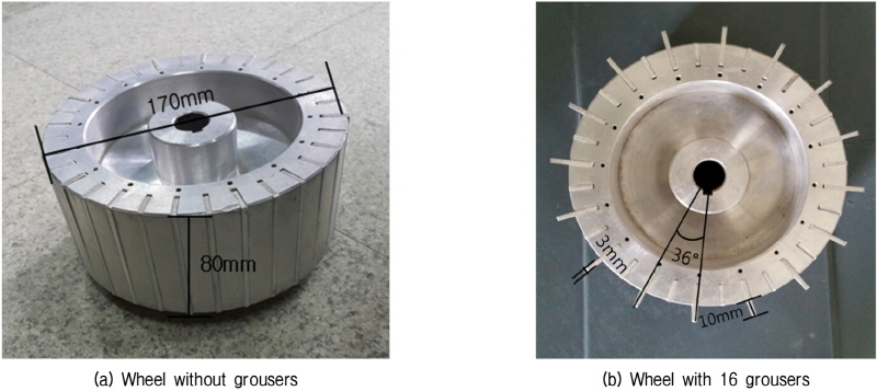
A wheel shown in Fig. 5 was designed in Korea Automotive Technology Institute (KATECH) for Korean lunar rover. Regardless of influence of wheel’s weight, size of wheel with diameter of 170 mm and width of 80 mm was adopted in this study. To compare effect of grousers on wheel’s traction performance, two kinds of cylinder aluminum wheels with 16 grousers (height of 10 mm, spacing of 36° and thickness of 3 mm) and without grousers were applied based on comparison with past experimental results. Pictures of wheels are shown in Fig. 6.
4.3 External Conditions
Due to the limitation of mobility of a lunar rover and energy supply, the rover is not available to move at a high speed. The maximum moving velocity of rover developed in KIST. In this experiment, to ensure stability of wheel’s motion performance on the testbed, a lower velocity of wheel was set to be 10 mm/s. As mass of Korean four-wheel rover is 20 kg, which means that the average vertical load on each wheel is 5 kg, vertical loads added to the wheel were controlled to be 6 kg through counterweight in this experiment. The experimental cases are shown in Table 3 below.
4.4 Experimental Procedure
In order to avoid sinkage in the locomotion, the slip ratio of exploring rovers should be well controlled, for instance, the maximum slip ratio of Mars rovers of USA is controlled to be less than 0.4 (Ding, 2010). In this study, to compare performance of rover wheel traction, the slip ratio was set to be from 0 to 50% and slip ratio was controlled by varying motion velocity of carriage motor. In order to ensure the repeatability and reliability and to reduce measurement error of the experiments, all the experiments were carried out three times under the same condition. The mean values were utilized to derive the correlation between drawbar pull, torque, sinkage and slip ratio, respectively.
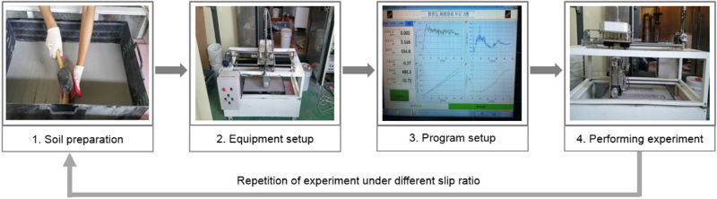
Fig. 7 shows the procedure of experiments. Before performing experiments, all sensors were calibrated and the test wheel size and the rover moving velocity and wheel angular velocity were considered as input parameters. Soil conditions were cautiously managed to be kept constant. During experiments, the value of drawbar, torque and sinkage were recorded from a computer program.
5. Results and Analysis
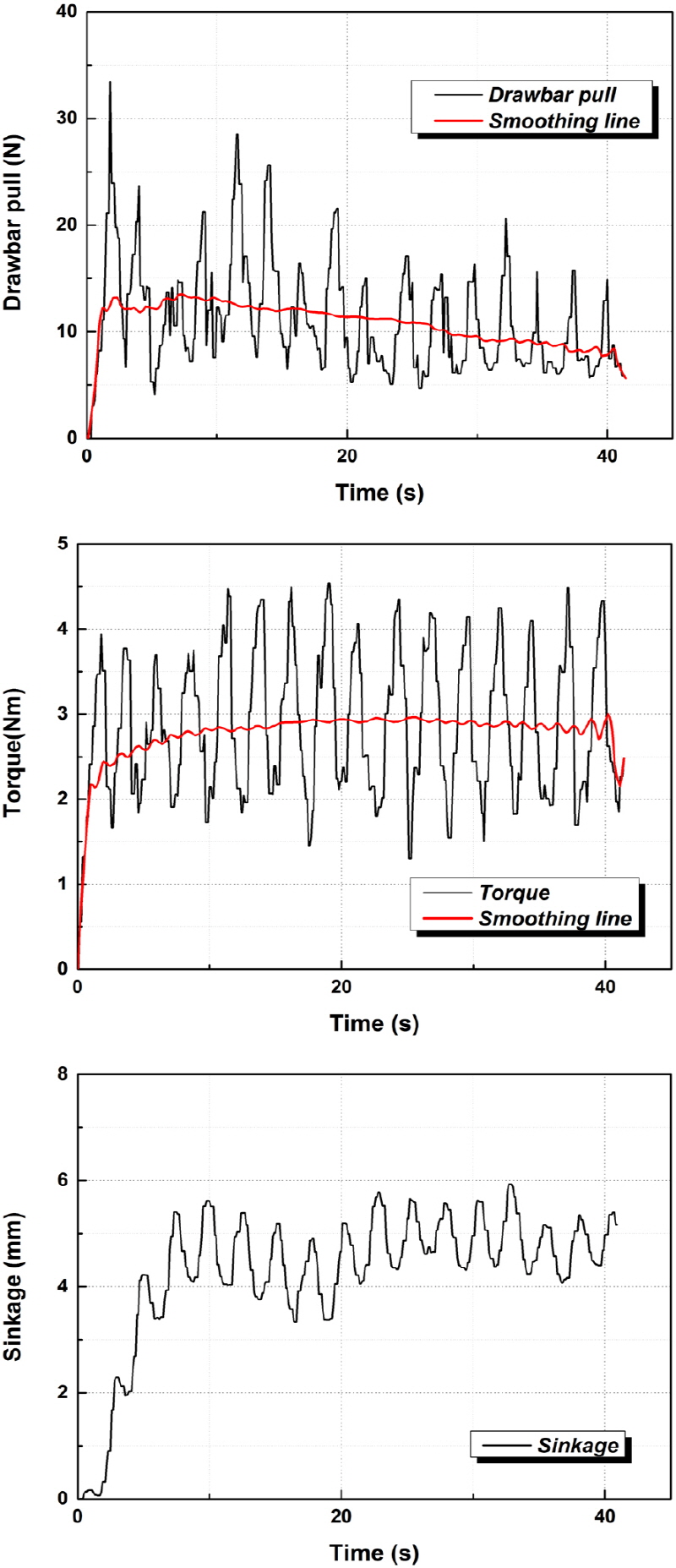
All the tests for the drawbar pull, torque and slip- sinkage were measured under slip of 0-0.5. Since the measured data of drawbar pull and torque have large fluctuation, the data of drawbar pull and torque were processed by using adjacent averaging smooth at point of window of 300. As data of sinkage did not fluctuated greatly, data of sinkage were not processed. The results are shown in Fig. 8. Each test was conducted around 40s. In the beginning stage, it takes about 10s for wheel interacting with soil to reach a steady data. Therefore, the data of drawbar pull, torque and sinkage from 10s to 40s at steady-state response were utilized to calculate the mean value and standard deviation in each case. The obtained data were adopted to plot the curve of drawbar pull, torque and sinkage as a function of slip ratio.
|
Fig. 8. Example of drawbar pull, torque and sinkage time histories (Vertical load 6 kg, wheel with grouser, slip ratio 0.2) |
5.1 Performance of Wheel on Rigid Plate
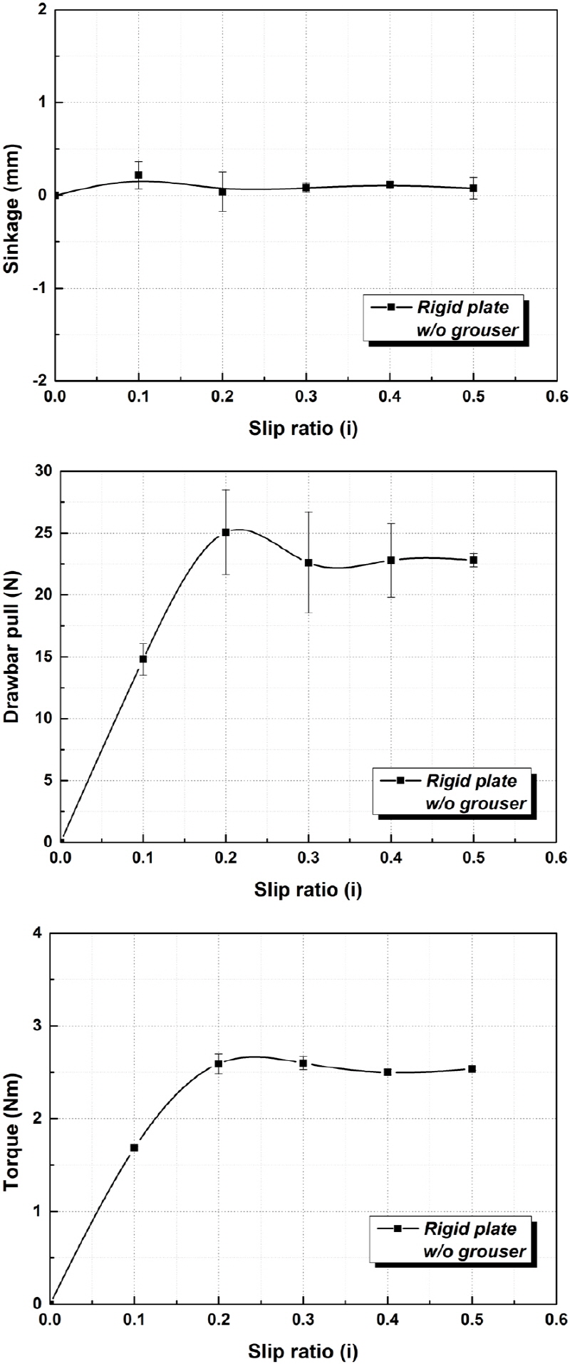
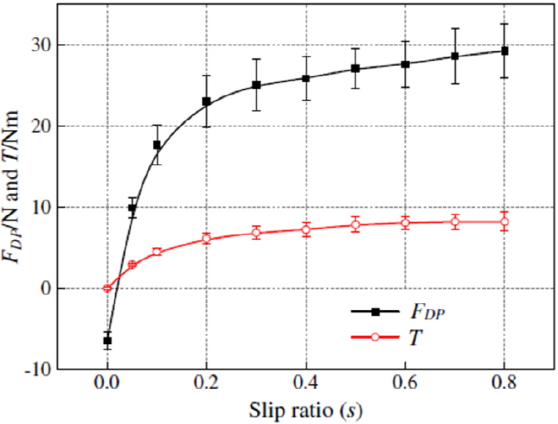
Before carrying out experiments on KLS-1, the pre-liminary tests were conducted on the rigid plate shown in Fig. 9. Drawbar pull, torque and sinkage were measured at vertical loads of 6 kg for the verification of single wheel testbed developed by KICT. Fig. 10 presents the results of drawbar pull, torque and sinkage value versus various slip ratio of a wheel without grouser, respectively. Because the experiments were conducted on the rigid plate, sinkge is nearly zero as shown in Fig. 10 (a). The graphs of Figs. 10 (b), (c) illustrate that torque and drawbar pull increase sharply with increasing slip ratio at between 0-0.2, and the maximum value of drawbar pull and torque are generated at slip ratio of about 0.2 and then gradually becomes converged similar to other research as shown in Fig. 11 (Ding et al., 2011). Therefore, this equipment was considered to be verified in terms of the performance evaluation for the single wheel.
5.2 Performance of Wheel Mobility on KLS-1
As wheel design is a key factor evaluated in this study, a series of experiments with 2 kinds of wheels (with grousers and without grousers) were performed on the KLS-1. While a wheel moves on the deformable terrain, tracks are generated.
Fig. 12 shows the picture of tracks for wheel with and without grousers under the slip ratio of 0.1, 0.2, 0.4 and 0.5, respectively. It can be seen that as the increase of slip ratio from 0.1 to 0.5, interval of tracks decreases and soil becomes denser. At slip ratio of 0.5, soil is disturbed heavily. Furthermore, interval of tracks at each slip ratio in Fig. 12 (a) is smaller than wheel without grousers shown in Fig. 12 (b) because grousers has effect on enhancing soil’s compactness. Whereas, at high slip ratio of 0.5, grousers digging into soil results in increasing soil’s disturbance when wheel entering into soil and leaving from the soil. According to tracks of wheel, Figs. 13 (a), (b) show the smoothing data of drawbar pull for wheel with grousers and without grousers under slip ratio of 0.1, 0.2, 0.4 and 0.5, respectively. Drawbar pull is developed by shear stress applied on the soil depending on soil’s density and strength. Value of drawbar pull increases depends on increment of slip ratios from 0.1 to 0.4, and most important factor is larger drawbar pull developed under denser soil while a wheel is spinning on the soil. On the contrary, drawbar pull decreases at slip ratio of 0.5, and the large slip causes the grousers digging the soil and stuck in the soil. As a result, distrurbance of soil reducing shearing on the interface of wheel and soil greatly leads to the decrement of drawbar pull.
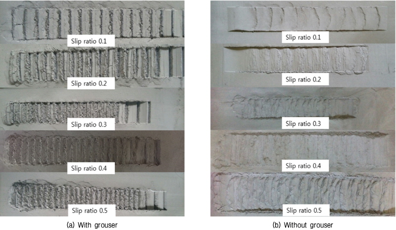
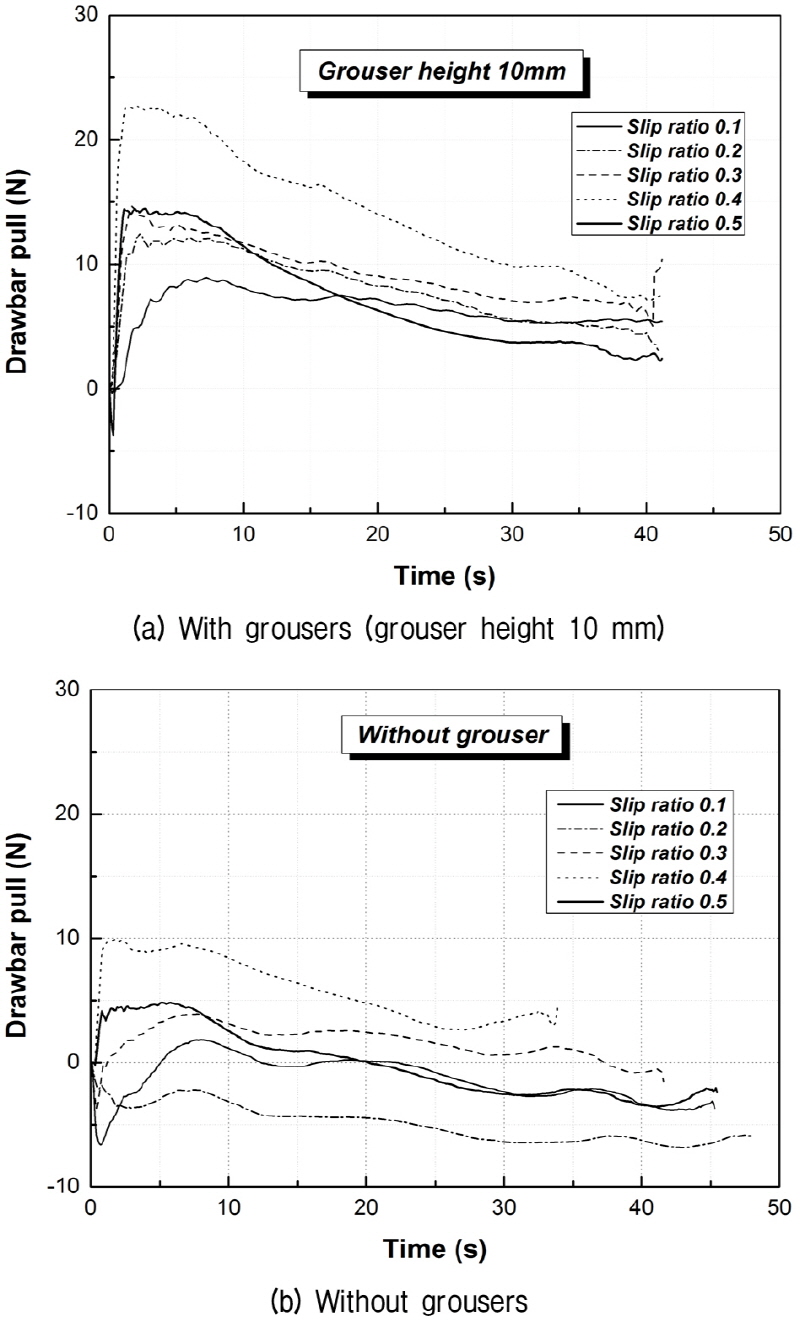
Fig. 14 shows the relation of drawbar pull, torque and slip-sinkage as a function of slip ratio for a wheel without grouser and with grouser of 10 mm height, 36° spacing and 3 mm thickness at vertical load of 6 kg. It can be observed in Fig. 14 (a) that sinkage of wheel increases with increasing slip ratio because the relative density of soil is low compared to the rigid plate. If the slip ratio is less than 0.2, the trend of two types of wheels is similar, however, at slip ratio of 0.5, value of sinkage for wheel with grousers is 1.68 times higher than smooth wheel It can be seen that grousers have not obvious effect on sinkage at low slip ratio. Whereas, if the slip ratio is greater than 0.2,
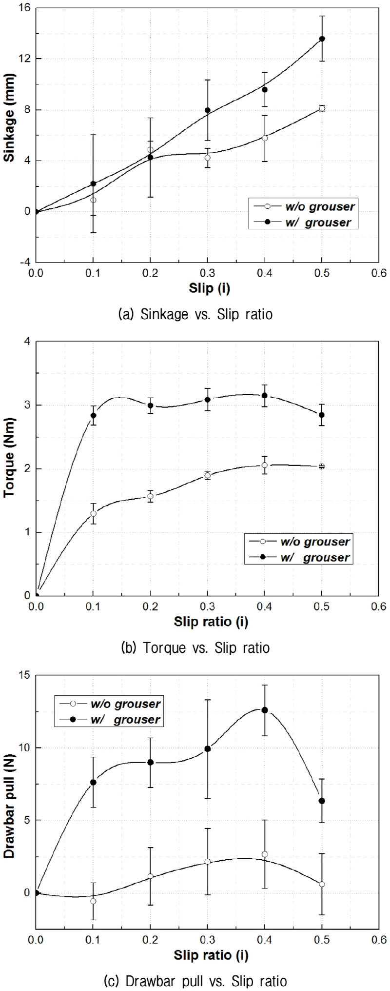
sinkage increases exponentially for the wheel with grousers. Under slip ratio of 0.5, wheel with grousers increased by 2.2 times from slip ratio 0.2, whereas wheel with grouser increased by 1.7 times. It can be explained that at less slip ratio, grouser has not obvious influence on slip sinkage, but the grouser’s effect of digging in the soil plays an important role of increasing motion resistance and sinkage. Figs. 14 (b), (c) that torque and drawbar pull increased rapidly with the increase of slip ratio from 0-0.1 at the initial phase and then after reaching a maximum value, torque gradually becomes converged. However, drawbar pull decreases with the increase of slip ratio from 0.4-0.5. At slip ratio from 0.4-0.5, decrement of shear stress caused by soil’s heavy disturbance leads to reducing drawbar pull. In addition, as the effect of grousers on digging into soil, the drawbar pull’s decrement of wheel with grousers is 3 times greater than wheel without grousers.
The results also indicate that the value of drawbar pull, torque and sinkage are higher in the case of wheel with grouser than without wheel. The peak value of torque on wheel with grousers is only 1.5 times more than smooth wheels. However, the peak value of drawbar pull is 4.7 times higher than wheel without grousers. It can be explained that grousers of wheel have an influence on traction performance of a wheel. Thrust of a wheel is obtained from shear stress developed by the interaction of wheel and soil. A wheel with grousers is able to generate larger thrust by increasing the shear stress while interacting on the soil to move the rover forward. The results could be utilized in the evaluation of drawbar efficiency for a rover.
6. Conclusion
In this study, a single wheel testbed was developed and used to evaluate the traction performance of two lunar rover wheels (with grousers and without grousers) on Korean lunar soil simulants (KLS-1) whose geotechnical and physical properties were experimentally validated to be similar to real lunar soil and other lunar soil simulants. The traction performance parameters such as drawbar pull, torque and sinkage were measured by the single wheel testbed in order to evaluate the performance of the wheel under the normal load of 6 kg at the speed of 10 mm/s.
The tests performed on rigid plate were to evaluate the calibration of equipment and to compare with the experimental results on KLS-1. Torque and drawbar pull increased with slip ratio at from 0-0.2 and then were stabilized like the results in literature. In the case of the tests on KLS-1, wheel with grousers obtained much higher performance than smooth wheel at a small slip ratio. It can be seen that wheel configuration and terrain conditions significantly influence the motion performance of the wheel.
The results may be useful in optimizing wheel design and verifying preferable slip ratio for Korean planetary rover’s mobility performance. To analyze the optimum wheel configuration and evaluate the reliability of rover’s locomotion performance better, more experiments in terms of changing wheel grouser shape, wheel size, soil conditions and temperature conditions should be implemented in the future works.
