

1. Introduction
2. Numerical Approach and Extended Parametric Study
3. Effect of Rock Mass Conditions
4. Conclusions
1. Introduction
The impact of deep excavation works on the surround-ing environment has become a major concern. To minimize excavation-related problems such as wall collapse and to maximize economic efficiency for support design, it is necessary to clearly understand the behavioral characteristics of the ground and excavation walls and to have a clear understanding of ground-wall interactions.
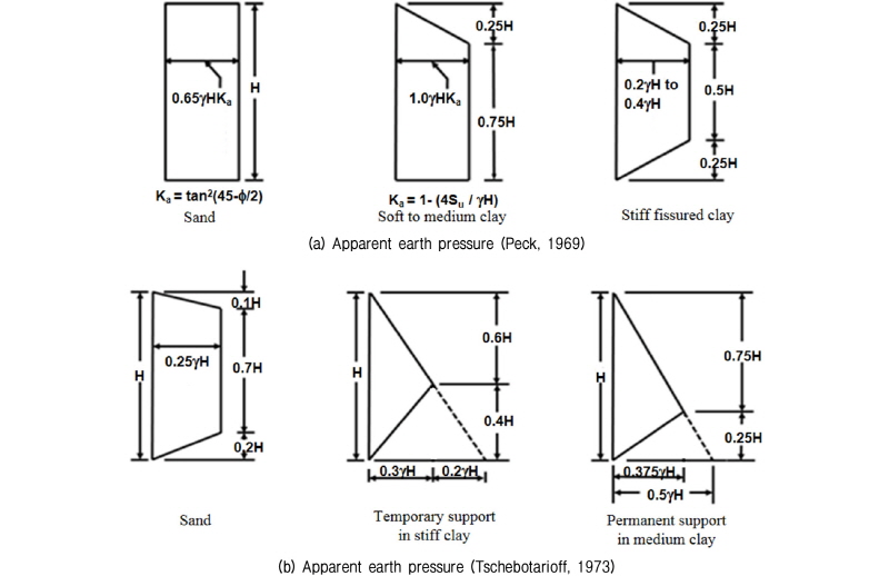
The earth pressure on the excavation walls caused by deep excavation works have been studied by many researchers through field measurements and physical model tests. Fig. 1 shows apparent earth pressure envelopes suggested by Peck (1969) and Tschebotarioff (1973), which are frequently used in practice for designing excavation walls soil ground. However, the existing studies were mainly carried out on sandy and clayey soils though ground is made up of not only soils but also rocks. Nevertheless, there are also some studies which measured the earth pressure on the excavation walls in multi-layered ground, including rocks (Chae and Moon, 1994; Jeong and Kim, 1997; Yoo and Kim, 2000). These studies only compare the earth pressure measured in multi-layered soils with Peck’s earth pressure and the effect of groundwater and earth pressure coefficient as well as joint condition (joint inclination angle and joint shear strength) were not examined. Few studies have examined the earth pressure in rock strata by considering ground-wall interactions and joint characteristics, which are important factors influencing the magnitude and distribution of the earth pressure in jointed rock mass. This might be due to the general misunderstanding that rock strata represent a better condition than soil ground. Recently, to better understand the earth pressure on an excavation wall in jointed rock mass, Son (2013), Son and Park (2014), and Son and Adedokun (2015) presented physical and numerical study results of the earth pressures in jointed rock mass, con-sidering various rock, joint, and support conditions. The results clearly showed that the earth pressure can be higher for rock strata than soil ground when the rock and joint characteristics are under unfavorable conditions, such as a joint condition that induces sliding and a weathered joint and rock condition. On the other hand, the earth pressure might be much lower than the soil ground when the rock and joint conditions are favorable.
This study extended the previous study (Son et al., 2015), focusing on the effect of groundwater condition under different rock type, joint inclination angle, and earth pressure coefficient. Extended numerical parametric studies were conducted by varying the groundwater con-dition together with the rock type, joint inclination angle, and earth pressure coefficient. The results from this study are expected to provide a better understanding of the earth pressure on the excavation wall in a jointed rock mass that can experience different rock mass coditions.
2. Numerical Approach and Extended Parametric Study
The applied numerical approach in this study is similar to the previous study (Son and Park, 2014), and the following gives a brief description. The approach was verified by the numerical simulation of a physical model test (Figs. 2 and 3). The numerical approach was extended to this parametric study, which considered the effect of different groundwater condition (no groundwater and groundwater with an impermeable wall) and earth pressure coefficient as well as rock types and joint inclination angles on the magnitude and distribution of earth pressure against the excavation wall in jointed rock masses. Table 1 summarizes the consider conditions in this study. The groundwater table was assumed to be at the ground surface.
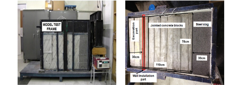

Table 1. Controlled parameters for numerical analyses 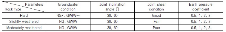 | |
*: No groundwater, **: Groundwater with impermeable wall | |
To assess the characteristics of rock masses governed by joints, this study adopted 2-D Universal Distinct Element Code (UDEC, 2004), which allows for large displacements between blocks. The rock blocks, wall and struts were simulated as separate elastic elements. The joints between the rock blocks and the interfaces between walls and rocks were modeled using the Coulomb slip model in which when the contact shear stress exceeds the contact shear strength the contact loses strength and sliding occurred. A fully coupled mechanical-hydraulic analysis was performed, in which joint porewater pressures affected the mechanical computations. The coupled behavior was examined using the method of fluid flow in joints provided by the DEM code.
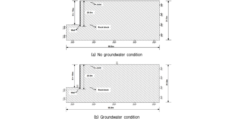
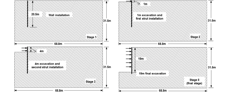
The analysis model was 68.8 m × 31.5 m and the excavation wall was installed at the depth of 20.5 m (Fig. 4). The excavation width was assumed to be 20 m and the final excavation depth was 19 m. A strut- supported system was used because the apparent earth pressure (Peck, 1969), which was compared with this paper’s results, was obtained from many sets of compre-hensive measurements of the strut load in strut-supported excavation walls for soil ground.
The strut stiffness (80 MN/m/m), which is a typical struct stiffness of the vertical spacing of 3 m, was determined from the properties of the strut member as shown below.
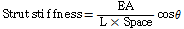
where A is the cross sectional area of the strut, E is the elastic modulus of the strut, L is the half of the strut length, Space is the strut horizontal spacing, θ is the installation angle of the strut (zero in horizontal installation).
The joint inclination angle was measured in the anti-clockwise direction from the horizontal plane, and the joint spacing was assumed to be 1 m. For each of the cases, the analysis was carried out using soldier pile and timber lagging wall. In order to reflect the general exca-vation procedures in the field, eight excavation stages were conducted to obtain the distribution and magnitude of earth pressure. Before the first excavation was carried out, the initial equilibrium was obtained with the at-rest earth pressure coefficient. At this stage, the boundary condition was a roller at each end of the two vertical boundaries and at the bottom boundary. After ensuring the initial equilibrium condition, all displacements were reset to zero and the wall was installed at a depth of 20.5 m. The first excavation was conducted up to 1.0 m, followed by the installation of the first strut at 0.5 m over the excavation line. After the first excavation, there was additional excavation work every 3 m, which was followed by the strut installation at every 3 m interval (which is 0.5 m above each excavation line). Wall stabili-zation was ensured after each excavation stage. The final excavation was conducted up to 19.0 m, and no strut was installed in the final stage (see Fig. 5). Other analyses were also carried out for different groundwater conditions and earth pressure coefficients using the same procedures discussed above.
The shape of typical excavation wall (i.e. soldier pile and timber lagging wall) might have little effect on the earth pressure and wall displacement in the field as long as the flexural stiffness of the wall is equivalent. However, in a numerical analysis the shape may have a considerable influence on the results because of a stress concentration in modeling. To address this issue, this study transformed the excavation wall into a simple section to represent the equivalent flexural stiffness of the wall (see Fig. 6) using the method as shown below.

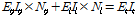
where Ep is the elastic modulus of the soldier pile, El is the elastic modulus of the timber lagging, Et is the elastic modulus of the transformed section, Ip is the second moment inertia of the soldier pile, Il is the second moment inertia of the timber lagging, It is the second moment inertia of the transformed section, Np is the number of the soldier pile per unit meter, and Nl is unity.
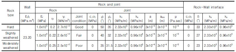
Table 2 shows the properties of the wall, rocks, joints, and interfaces used in numerical analysis. The assessment of the properties was discussed in detail by Son and Yoon (2011).
3. Effect of Rock Mass Conditions
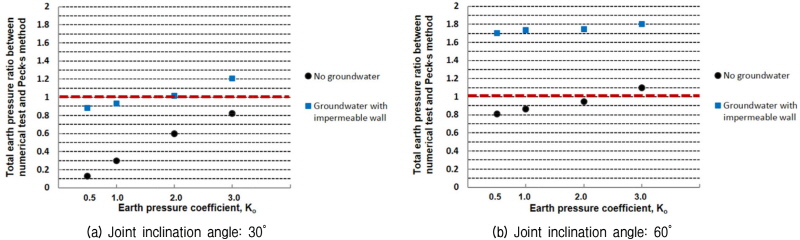
Figs. 7 and 8 compare the distributions of the apparent earth pressures induced on the excavation walls for hard rock at the joint inclination angles of 30° and 60° res-pec-tively under different groundwater conditions and at-rest earth pressure coefficients. In the figures, the induced earth pressures were represented in terms of apparent earth pressures in which the magnitude and distribution of earth pressures on the excavation wall were inferred from the strut axial loads in the same way as Peck (1969). In addition, the induced apparent earth pressures in jointed rock masses were compared with Peck’s apparent earth pressure for sand ground with a friction angle of  = 35°. The medium dense sand ground with a friction angle of
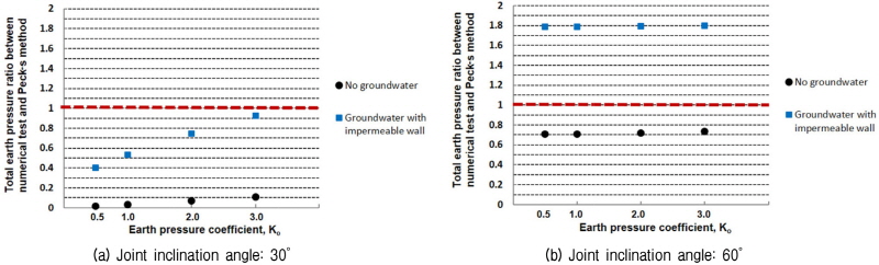
  = 35° was simply chosen because the empirical earth pressure envelope by Peck for the ground is relatively simple and can be compared directly and easily with the results of numerical parametric studies for jointed rock masses. The apparent earth pressure ratio in the figures represents the ratio of the induced earth pressure for jointed rock mass to Peck’s earth pressure for the sand ground. It is quite meaningful to compare the results of the earth pressures in this study with a specific soil ground because a practitioner can obtain useful and intuitive information of the earth pressures in jointed rock masses by simply comparing with the soil earth pressure. A practitioner can easily estimate the earth pressure in a jointed rock mass using the normalized earth pressure ratios between the jointed rock masses and the sand ground with a friction angle of 35°. Fig. 9 compares the total earth pressure ratios (the area of an induced apparent earth pressure distribution envelope divided by the area of Peck’s apparent earth pressure envelope) of the induced earth pressures from numerical analysis with that from Peck’s empirical earth pressure for the sand ground varying joint inclination angle.
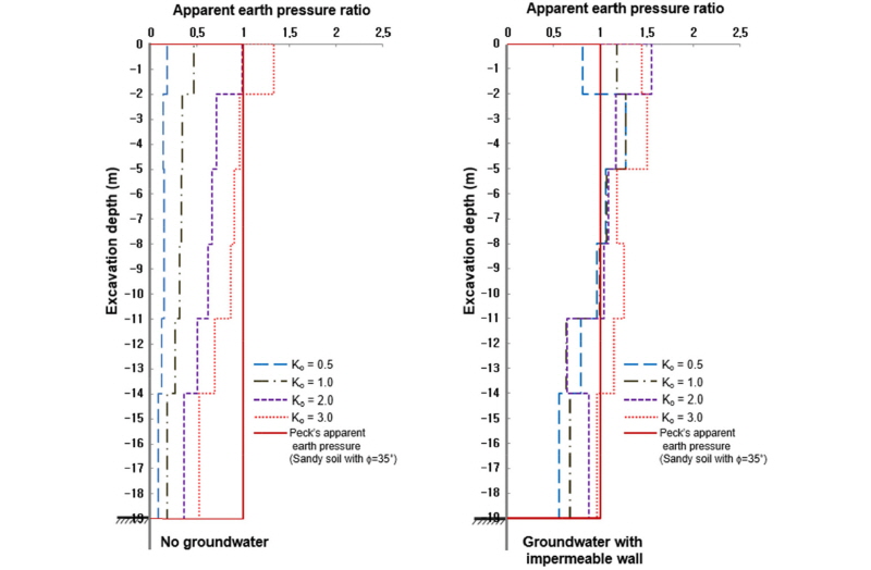
For a joint inclination angle of 30°, the apparent earth pressure ratio was the highest at the top part of the excavation wall and decreased along depth under no groundwater condition regardless of the at-rest earth pressure coefficient. The total earth pressure ratios ranged from 0.02 to 0.11. In contrast, the earth pressures of the groundwater con-dition with an impermeable wall increased significantly and proportionately to the at-rest earth pressure coefficient. The increase in earth pressure under the condition with groundwater can be attributed to the increase in joint shear stress due to the joint inclination and the decrease in joint shear strength due to the pore water pressure induced by the ground-water table at the ground surface. The earth pressure was also higher at the upper part of the wall under the ground-water condition and it decreased along depth. The total earth pressure ratios ranged from 0.4 for an earth pressure coefficient of 0.5 to 0.92 for an earth pressure coefficient of 3.0.
These results suggest that the earth pressure in a jointed rock mass is strongly dependent on the groundwater condition, at-rest earth pressure coefficient, and joint inclination angle.
For a joint inclination angle of 60°, where joint sliding was induced, the apparent earth pressures under no ground-water condition were significantly higher than those of the joint inclination angle of 30° under the same condition. The effects of the earth pressure coefficient were not significant when joint sliding was induced (see Figs. 8 and 9). In addition, the apparent earth pressure ratio was the highest at the top part of the excavation wall under no groundwater condition and decreased along depth but it tended to increase along depth under the groundwater condition with an impermeable wall. The total earth pressure ratios ranged from 0.74 for an earth pressure coefficient of 0.5 to 0.75 for an earth pressure coefficient of 3.0. The earth pressures of the groundwater condition with an impermeable wall increased significantly, but they were irrelevant to the at-rest earth pressure coefficient due to the effect of joint sliding. The total earth pressure ratios ranged from 1.78 for an earth pressure coefficient of 0.5 to 1.80 for an earth pressure coefficient of 3.0.
These results suggested that joint sliding increased the earth pressure significantly but it decreased the effects of the earth pressure coefficient.
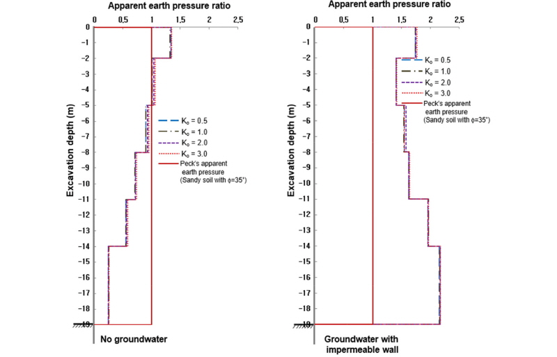
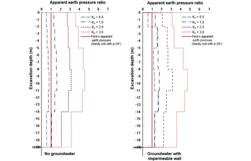
Figs. 10 and 11 compare the distributions of the apparent earth pressures induced on the excavation walls for slightly weathered rock at the joint inclination angles of 30° and 60° respectively under different groundwater conditions and at-rest earth pressure coefficients. In addition, the apparent earth pressures were compared with Peck’s apparent earth pressure for sand ground with a friction angle of  = 35°. Fig. 12 compares the total earth pressure ratios of the induced earth pressures from numerical analysis with that from Peck’s empirical earth pressure for the sand ground varying joint inclination angle.

For a joint inclination angle of 30°, the apparent earth pressure ratio was also the highest at the top part of the excavation wall and decreased along depth under no groundwater condition regardless of the at-rest earth pressure coefficient. But the apparent earth pressures for all the earth pressure coefficients were significantly higher when compared to those of hard rock with a joint in-clination angle of 30°. The total earth pressure ratios of the no groundwater ranged from 0.13 for an earth pressure coefficient of 0.5 to 0.83 for an earth pressure coefficient of 3.0. For the groundwater condition with an impermeable wall, the earth pressure distribution was similar to hard rock in shape, but the magnitude of the induced earth pressure was much higher and the total earth pressure ratios ranged from 0.88 to 1.21.
The results suggested that the effects of groundwater on the earth pressure decreased with increasing at-rest earth pressure coefficient, Ko. This is different from hard rock, where the effect was opposite. In other words, the effects of groundwater on earth pressure are influenced by the rock and joint conditions.
For a joint inclination angle of 60°, where joint sliding was induced, the apparent earth pressures under the no groundwater condition were higher than those of the joint inclination angles of 30° under the same condition. A more significant increase took place at lower earth pressure coefficients (see Figs. 11 and 12). The effects of the earth pressure coefficient were less significant when joint sliding was induced. In addition, the apparent earth pressure ratio was highest at the top part of the exca-vation wall under no groundwater condition and decreased along depth, which was also observed in hard rock, but it was similar along depth under the groundwater condition with an impermeable wall. For no groundwater condition the total earth pressure ratios ranged from 0.81 for earth pressure coefficients of 0.5 to 1.1 for an earth pressure coefficient of 3.0. The earth pressures of the groundwater condition with an impermeable wall were much high and the total earth pressure ratios ranged from 1.7 to 1.8, which were similar to those of hard rock for the groundwater condition with an impermeable wall.
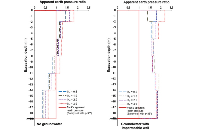
Figs. 13 and 14 compare the distributions of the apparent earth pressures induced on the excavation walls for moderately weathered rock at the joint inclination angles of 30° and 60° respectively under different ground-water conditions, wall permeability conditions, and at-rest earth pressure coefficients. In addition, the apparent earth pressures were compared with Peck’s apparent earth pressure for sand ground with a friction angle of  = 35°. Fig. 15 compares the total earth pressure ratios of the induced earth pressures from numerical analysis with that from Peck’s empirical earth pressure for the sand ground varying joint inclination angle.
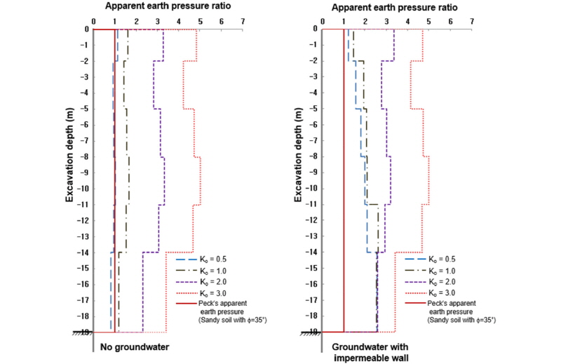
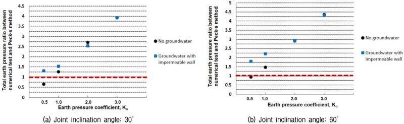
For a joint inclination angle of 30°, the induced earth pressures for all the earth pressure coefficients were signi-ficantly higher than those of hard and slightly weathered rocks due to the higher tendency of block displacement in moderately weathered rock. The results showed that earth pressures increased constantly with the increase of the earth pressure coefficient and the increase rate was much higher than that in slightly weathered rock. The effects of groundwater on the earth pressure were much lower than those of hard and slightly weathered rocks and there was no groundwater effect at the high earth pressure coefficients of 2.0 and 3.0. The apparent earth pressure ratio was the highest at the middle part of the excavation wall regardless of the earth pressure coefficient and groundwater conditions. The total earth pressure ratios between the induced earth pressure and Peck’s earth pressure ranged from 0.65 (1.31 for the groundwater condition with an impermeable wall) for an earth pressure coefficient of 0.5 to 3.93 (3.93 for the groundwater condition with an impermeable wall) for the earth pressure coefficient of 3.0.
For a joint inclination angle of 60°, although joint sliding was induced and more evident increase occurred at lower earth pressure coefficients (see Figs. 14 and 15), the apparent earth pressures were relatively similar to those of the other joint inclination angles, which was different from the hard and slightly weathered rocks. These results suggest that the effects of joint sliding decreased as the rock and joint conditions deteriorated. The effects of groundwater on the earth pressure were similar to those of the joint inclination angle of 60°. For no groundwater condition, the apparent earth pressure ratio tended to be high at the middle part of the excavation wall regardless of the earth pressure coefficient and groundwater conditions, but it depended on the earth pressure coefficient under the groundwater condition with an impermeable wall. The total earth pressure ratios between the induced earth pressure and Peck’s earth pressure ranged from 0.94 (1.79 for the groundwater condition with an impermeable wall) for an earth pressure coefficient of 0.5 to 4.38 (4.38 for the groundwater condition with an impermeable wall) for an earth pressure coefficient of 3.0. For moderately weathered rock the highest apparent earth pressure ratio was observed at the middle part of the wall regardless of groundwater and joint sling conditions.
4. Conclusions
The magnitude and distribution of the earth pressure on the excavation wall in jointed rock masses were investi-gated. The controlled parameters included groundwater condition, rock type, joint condition, and earth pressure coefficient. The following conclusions were made:
(1)The magnitude and distribution of the earth pressure on an excavation wall in a jointed rock mass are highly affected by the groundwater condition and earth pressure coefficient, together with the joint inclination angle and rock type. In addition, the induced earth pressure in a jointed rock mass can be significantly different from that in soil ground.
(2)As the rock and joint conditions were weathered more, the induced earth pressure increased, the effect of groundwater decreased, the effects of earth pressure coefficient increased, and the effects of joint inclination angles decreased.
(3)When joint sliding was induced, the sliding effect was more significant in hard rock and the effect was relatively small in moderately weathered rock. In moderately weathered rock, the high deformability of the rock and joint decreased the effect of joint inclination angle and groundwater.
(4)When the joint inclination angle was 30° in hard rock and good joint conditions, the induced earth pressure under groundwater condition increased signi-ficantly with the increase of earth pressure coefficient, but the effect of earth pressure coefficient on the induced earth pressure was very small when joint sliding was induced. On the other hand, when the rock and joint conditions were moderately weathered, the effect of groundwater on the induced earth pressure was only evident at a lower earth pressure coefficient regardless of the joint inclination angle.
(5)Apparent earth pressure ratio was higher at the upper part of the excavation wall for hard and slightly weathered rocks regardless of groundwater condition but the feature disappeared when joint sliding was induced at the joint inclination angle of 60°. For moderately weathered rock the highest apparent earth pressure ratio was observed at the middle part of the wall regardless of groundwater and joint sling conditions.
